SIMECA: SDN-based IoT mobile edge cloud architecture
1. Tutorial Overview
This tutorial will show you how to initiate a SIMECA profile in PhantomNet and interact with SIMECA. At the end of the tutorial, you will have a sense of what SIMECA IoT mobile edge cloud is and how it works. You will be walked through experiments to (1) Attach a Nexus 5 device to SIMECA's core network and access a service in SIMECA's mobile edge cloud, (2) Attach an emulated User Equipment (UE) to SIMECA and set up a peer-to-peer connection between the emulated UE and the Nexus 5, (3) Perform a S1 seamless handover on the Nexus device while keeping an on-going peer-to-peer connection.
2. What is SIMECA?
SIMECA is a mobile core network that leverages SDN, NFV, and mobile edge cloud to provide low latency, low overhead for massive IoT devices. An overview of SIMECA is shown in figure 1: SIMECA architecture consists of three parts: SDN-enabled base stations (S-BS), SDN edge Network, and Edge Cloud. Here we will only provide an overview of SIMECA. If you are interested about the details, please refer to the paper.
- SDN-enabled base stations: are a set of base stations that are capable of SDN switch. The SDN-enabled base stations have OpenFlow interface to receive OpenFlow control messages from a SDN controllers (MCs) and install SDN rules in them. The S-BS classifies packets from the radio interface and passes them to the SDN edge network which delivers them to the server in the Edge Cloud. Applying SDN rules from an SDN controller, S-BS translates IP header of packets from User Equipment (UE) to a new IP header that is used by the SDN edge Network for forwarding.
- SDN edge Network: consists of multiple SDN switches that connects the S-BS to the Edge Cloud. The SDN switches forward UE's packets from the S-BS to the server that the UE is attached to. The SDN edge Network forwards packet using prefix matching on IP header.
- Edge Cloud: the edge cloud hosts both IoT services and NFV-based mobility functions. For example, Mobility Controller (MC) and Mobility Function (MF) are two component of the control plane of SIMECA are hosted in Edge Cloud. Using edge cloud, SIMECA reduces latency of both IoT services and SIMECA control plane. Also, the Edge Cloud allows flexibility and agility in deploying IoT services and SIMECA network functions.
- SIMECA Region: SIMECA consists of multiple regions each consists of three parts as above. The regions are interconnected by Gateway Switch. We envision a SIMECA region would correspond to a small metropolitan area with latency between S-BS and Edge Cloud is within several milliseconds.
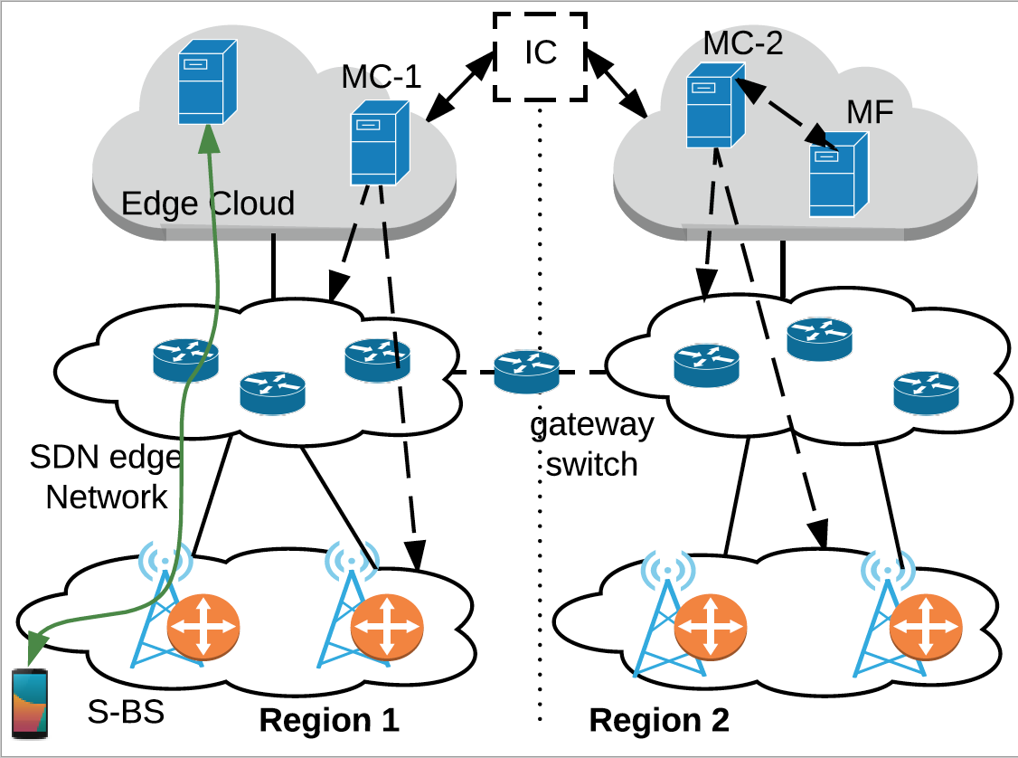
Figure 1: SIMECA overview
SIMECA proposes a forwarding scheme at the S-BS and edge network and a routing scheme to:
- Eliminate GTP tunneling in mobile core network to provide a low overhead control plane for IoT.
- Reduce packet header in the mobile core to reduce data plane overhead for small packets generated by IoT devices.
- Enable Peer-to-peer communications for IoT devices.
- Support mobility and enable a low end-to-end latency for both IoT services and control plane.
Please refer the paper for more details.
3. SIMECA prototype in PhantomNet
We package a prototype of SIMECA as a profile in PhantomNet. The topology of this prototype is shown below:
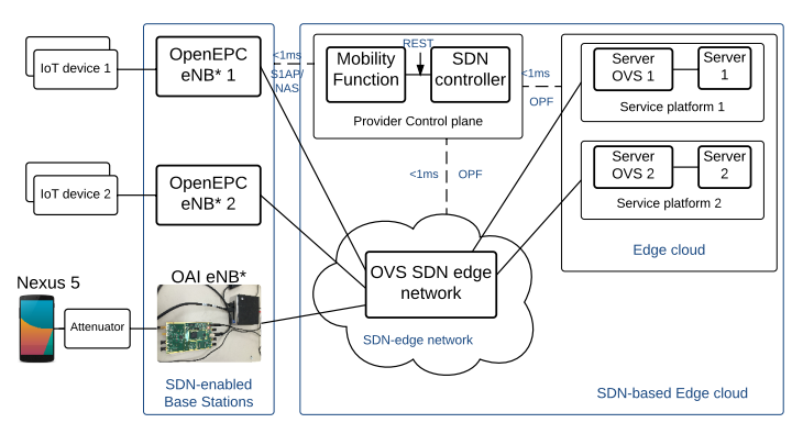
Figure 2: SIMECA prototype in PhantomNet.
The prototype consists of:
- S-BS: the S-BS has three base stations - two emulated modified OpenEPC base stations and one modified OpenAirInterface SDR eNodeB running on USRP-B210 hardware. The radio link between Nexus 5 and the SDR base station is an RF link. Each base station has a default route to an Open Vswitch. The Open Vswitch (OVS) enables SDN functionality for the base station.
- Open Vswitch SDN Edge Network: there is a simple OVS to mimic an SDN edge network. The switch performs shortest path forwarding to forward packets between S-BS and Edge Cloud.
- Edge Cloud: there is one normal Ubuntu 12.04 server and an OVS attached to it in the Edge cloud.
- SIMECA control plane: The control plane of SIMECA ( MC and MF) is hosted on an node running Ubuntu 12.04 together with the modified MME.
4. Before you start
You need to obtain a permission to use a disk image in this experiment. Therefore you need to request the permission by sending an email to our support. Please follow this link.
5. Instantiate SIMECA prototype
To create your SIMECA prototype, instantiate an experiment using "simeca-sdr" profile:
"Actions" --> "Start Experiments" --> "Change Profile" --> search for "simeca-sdr" --> "Select Profile" --> "simeca-sdr"
More detailed information about how to instantiate an experiment using a profile, please see this.
6. SIMECA's source code:
The source code for SIMECA is in /opt/simeca. This includes implementation of MC, MF, and scripts to run SIMECA. The code for OpenEPC is hidden because of license permission. The code for OAI eNodeB is on the Penb1 node in /usr/local/src/airinterface/openairinterface5g.
You are welcome to modify SIMECA's controller code (/opt/simeca/simeca_controller/). Just copy the code to your home directory and modify it. The code is under Apache License (https://www.apache.org/licenses/LICENSE-2.0).
7. Initialize SIMECA
To run SIMECA, we first need to configure and run the OVSes in S-BS and SDN edge network as well as generate UE's subscription information in Home Subscriber Service (HSS) and a topology of the network with port information for shortest path forwarding module.
We have a start script that configs and set up all information to run SIMECA. Because the script also executes remote command on other nodes in the experiment (using ssh), you need to pass in your authentication information (using flag -YA in ssh) when log in to the SGW node to make this remote execution possible (otherwise you'll see the script asks for log in password which should not happen):
Log into SGW node: ssh -YA <your sgw node>
Important!! There is a script to initialize SIMECA. Before running the script, you need to change the UE's IMSI in the script so that the UE's information is populated into HSS database and the UE can attach to the network. To obtain UE's ID, in your experiment website click on List View to see the list of your nodes. For example, if your experiment is allocated UE7 (UE8), your UE_ID would be 306 (307). Feed in the UE_ID in the script on the SGW node:
On SGW node: sudo /opt/simeca/SCRIPTS/init_ue.sh
Now you can initialize SIMECA:
On SGW node (normal user): cd /opt/simeca/SCRIPTS; ./demo_init.sh
8. Start SIMECA controllers
We need to start SIMECA's control plane before doing other experiments. The SIMECA controllers consist of MF and MC that are running on a node named SGW. To start (or restart) them:
On SGW node (normal user): cd /opt/simeca/SCRIPTS; ./demo_restart.sh
When the script runs you will see the MME/emulated EnodeBs/MC/MF are restarted. At then end of the script, you'll see the MC is running and waiting for requests from MF (figure 3).
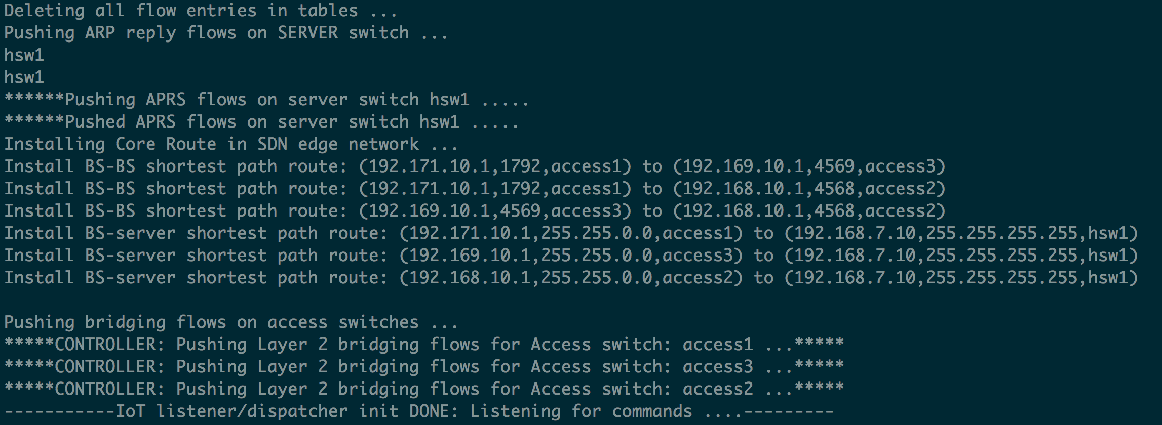
Figure 3. SIMECA controller started and is waiting for connection requests.
9. Scenario 1: Client-to-server connectivity
Step: Attach Nexus 5 to SIMECA's IoT core network.
In this first experiment we will see how SIMECA sets up a client-to-edge cloud server connection between a Nexus 5 and a server in the edge cloud. We'll need to run the OAI eNodeB by:
On Penb1 node: /usr/local/src/airinterface/openairinterface5g/SCRIPTS/run_lte_soft_modem.sh
The above script starts the OAI eNodeB. Once starts, the eNodeB will broadcast beacons and the Nexus 5 will automatically connect (figure 4). If the Nexus 5 does not try to attach to the eNodeB, try restart the Nexus 5. To restart the Nexus 5, log into adb-tgt node, and do:
On adb-tgt node: pnadb -a; adb reboot
After the Nexus 5 reboots and attaches to the eNodeB, you should see radio logs on the Penb1 as well as a note one the MC saying it installed a client-to-server path for the Nexus 5. The MC's log also shows the IP of the server that the Nexus 5 connected to and the Nexus 5's reachable IP address (figure 5).
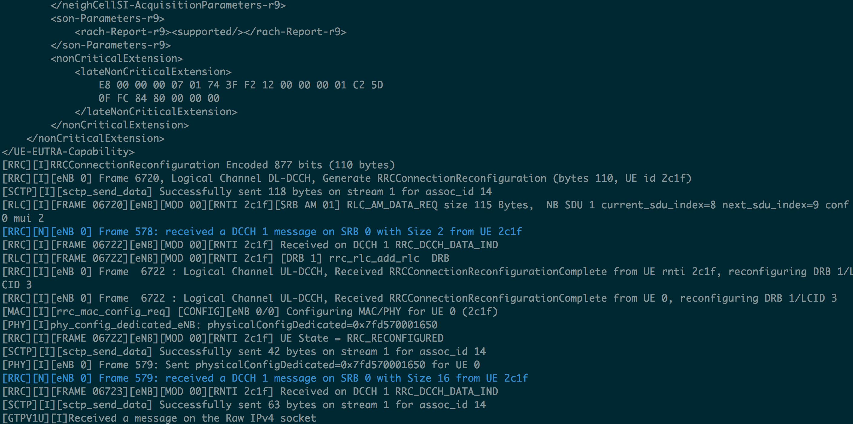
Figure 4. Nexus 5 attached to the network successfully.
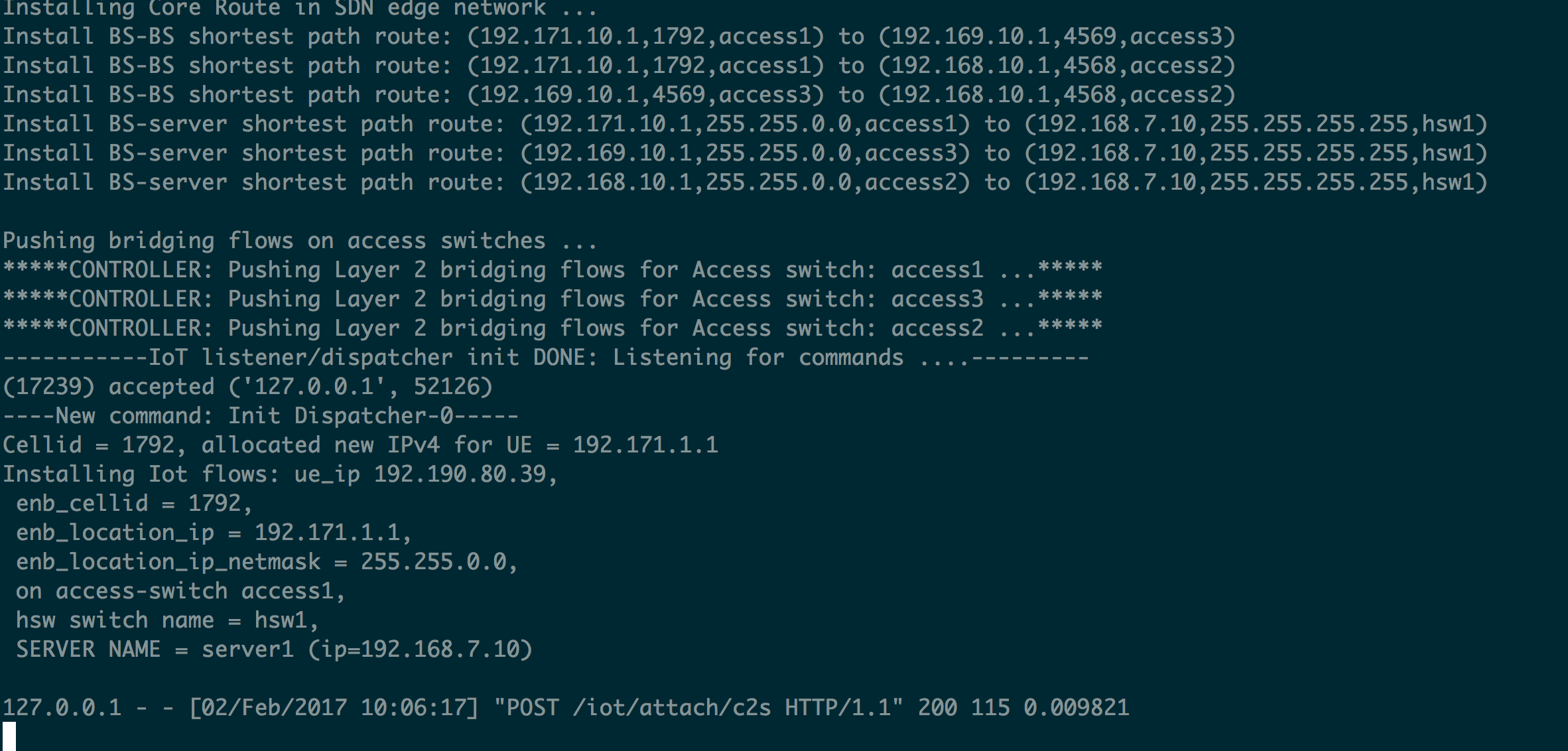
Figure 5. SIMECA controller shows it accepted a C2S connection from Nexus 5 (and the Nexus 5 device ID - IP address).
Step: Nexus 5 ping IoT server in edge cloud.
After the Nexus 5 connects to SIMECA, we can ping the server from Nexus 5. You should see around 15ms RTT from the Nexus 5 to the server. Notice that most of the latency comes from the radio latency.
On Adb-tgt node: pnadb -a; adb shell ping -c10 192.168.7.10
10. Scenario 2: Peer-to-peer connectivity
Step: Attach emulated UE to SIMECA.
To attach emulated UE to SIMECA, we need to trigger an Attach procedure on the emulated UE:
1. Log into client1 node via users.phantomnet.org: ssh -YA users.phantomnet.org
2. Attach to MM screen in client1: /opt/OpenEPC/bin/mm.attach.sh
3. (Inside the MM's screen) Trigger a network attach for the emulated UE: mm.connect_l3 LTE
Step: Peer-to-peer connection between Nexus 5 and emulated UE.
When the emulated UE attached, you should see that SIMECA sets up a peer-to-peer connection between the Nexus 5 and the emulated UE (the initialize script hardcoded in SIMECA configuration that SIMECA needs to set up this peer-to-peer connection always). In the UE's screen (mm screen), take note of the IP address the MC assigned to the emulated UE during attach (figure 6).
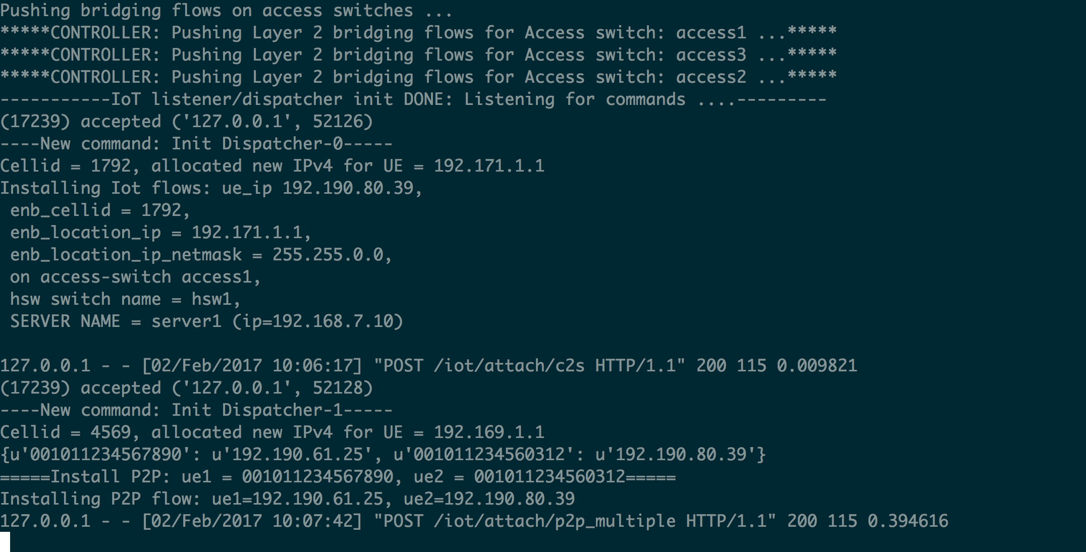
Figure 6. SIMECA's log showing a P2P connection between the Nexus 5 and the emulated UE was set up.
Once the emulated UE attached and the SIMECA controller finishes installing route, you can ping the emulated UE from the Nexus 5 (using the emulated UE's IP address in the UE's screen). You should see also around 13ms RTT.
On Adb-tgt node: adb shell ping <emulated UE's IP address (obtained in MC when the emulated UE attached).>
11. Scenario 3: Seamless handover
In this experiment we will let the emulated UE perform a seamless S1-handover while having an on-going connection with the Nexus 5. During the handover, you will see the emulated UE moves from eNodeb2 to eNodeb3 while the Ping session is not interrupted.
First, you need to start eNodeb3 which is the target eNodeB for the handover:
1. Log into enb3 node.
2. Start eNodeB: /opt/OpenEPC/bin/enodeb.start.sh
Second, while keeping the P2P Ping session in the last step, trigger a S1-handover on eNodeB2 by:
1. Log into enb2 node.
2. Attach to eNodeB's screen: /opt/OpenEPC/bin/enodeb.attach.sh
3. Perform S1-handover: enodeb.utah_intra_lte_handover 001011234567890 01 4569 192.168.3.32
The log on the emulated eNodeB will show that the emulated UE handed over from eNodeB2 to eNodeB3 (figure 7). While the handover happens, the Nexus 5 is still pinging the emulated UE just fine (without packet lost). This demonstrates seamless handover functionality in SIMECA.
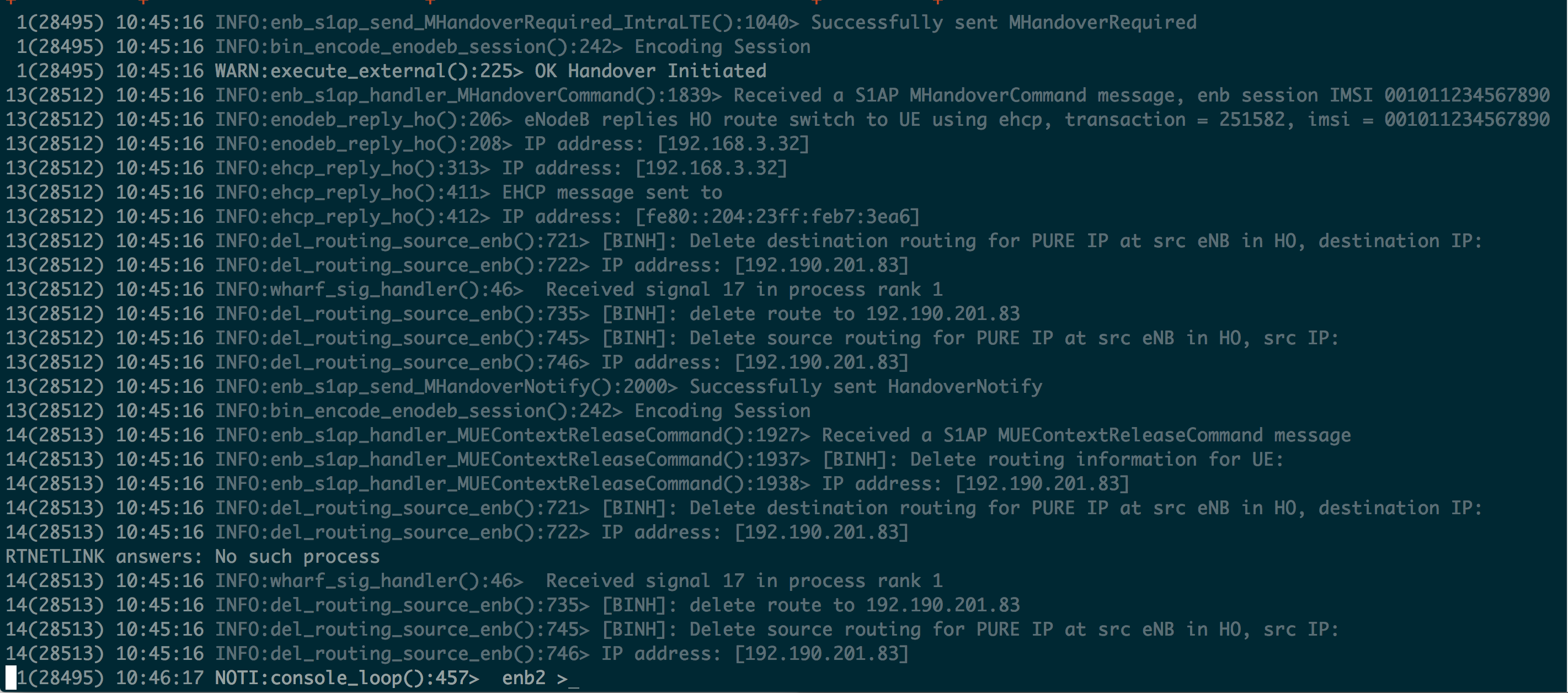
Figure 7. EnodeB2's log showing S1-HO was performed successfully.
12. Conclusion
This tutorial walked you through the steps to instantiate a prototype of SIMECA using a prepackaged profile in PhantomNet. It show steps to repeat several experiments to demonstrate basic functionality of SIMECA: low latency client-to-server connectivity, low latency peer-to-peer connectivity, and seamless mobility. By walking you through the tutorial, we hope you had a better sense of what SIMECA is, how it works, and from that develop your own ideas of integrating SDN in mobile networks.
13. Acknowledgement
We develop our SDN-based base station based on OpenAirInterface SDR eNodeB implementation and Open Vswitch. Our emulated base station and MME are based on OpenEPC implementation. If you have questions please contact: binh@cs.utah.edu.
